Practical solutions of varied problems of propulsion
ONE of the most interesting parts of an aeroplane is the airscrew, the mechanism which converts the engine energy into the work which has to be done to drive the aeroplane against the air resistance due to its motion. An airscrew derives its thrust, or driving force, from the reaction of the air which it pushes backwards.
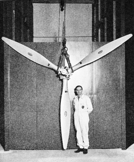
CONTROLLABLE-PITCH AIRSCREW manufactured by the De Havilland Aircraft Co. Ltd, under the Hamilton patents. This three-bladed airscrew is designed for an aero engine of 1,009 horse-power. It has a diameter of 13 feet and weighs 360 lb. The pitch of the blades can be altered as required for take-off, climb, or high-speed level flight.
The blades of an airscrew revolving at high speed form what is known as an airscrew disk. In operation there is a suction over the front surface of the airscrew disk and a pressure over the back surface. As the airscrew moves forward, the suction at the front draws air towards the airscrew, so that the quantity of air flowing through the airscrew disk is greater than the quantity which would flow through a circular ring of the same diameter as the airscrew and moving forward with the same speed.
The pressure at the back gives additional energy to the air passing through the airscrew, and as this energy eventually appears as energy of motion, the air sucked into the airscrew increases in speed as it flows through the disk.
Efficiency is measured by the ratio of the rate of useful work done to the rate at which energy is supplied. High efficiency can be obtained only when the speed at which air is sucked into the airscrew is small compared with its forward speed. For a given forward speed a given thrust is most efficiently developed when the largest possible quantity of air flows through the airscrew. It is therefore advantageous to make the diameter of an airscrew as large as possible; but, in practice, considerations of weight, strength and ground clearance impose limits on the maximum diameter that can be used.
The blades of an airscrew have, except near their roots, good aerofoil forms. The blades resemble twisted aerofoils, both the angle of twist and the blade thickness decreasing from the root outwards. The manner in which the blades work can best be illustrated by considering what is happening on an element, a thin section of the blade, contained between two planes at right angles to the length of the blade. Such an element is represented in Fig. 1. Because of the rotation about the airscrew axis, the element moves in the direction PQ with a velocity which can be represented by the length of PQ. But the element moves forward with the aeroplane and also sucks in air, so that, in addition to the rotational velocity, there is an axial velocity which can be represented by the line QR. The sum of these two velocities PQ and QR is the velocity PR. The element behaves, therefore, as if it were an aerofoil, or an aeroplane wing, inclined at an angle SPR, called the angle of incidence, to the local air and moving through the air with a velocity PR. When a blade section has a good aerofoil shape, and moves through the air at a small angle of incidence, it has a large lifting force at right angles to a direction of motion, at the expense of the small resistance, or drag, as it is commonly called, opposing the motion. A large lift force, L in Fig. 1, therefore acts on the element in a direction at right angles to PR, and a small drag force D in the direction RP. The resultant of these two forces, obtained by the parallelogram of forces, can be resolved into a thrust force acting in the direction of a forward motion QR, and a resisting force in the direction QP opposing the rotation of the element.
FIG. 1. HOW THE BLADES WORK can best be shown by a diagram of what happens to a section, or element, of an airscrew. The aerofoil in the diagram represents the section of a blade contained between two planes at right angles to the length of the blade. Because of the rotation about the airscrew axis, the element moves in the direction PQ. The element also has a forward velocity QR, so that the effective velocity is PR. In this position the element acts as an aerofoil, the angle of incidence being SPR. This gives a lifting force and a drag D.
The sum of the thrust forces acting on the blades gives the thrust of the airscrew; and the torque, or turning moment, which the engine must supply to drive the airscrew, depends on the magnitude of the resisting forces. High efficiency is possible only when the elements of the blade are working at angles of incidence (SPR in Fig. 1) which give high values of the ratio of the lift force L to the drag force D. The rotational velocity PQ increases with the distance of the element from the axis of rotation, so that the angle RPQ decreases with this distance, and the angle SPQ, known as the blade angle, must also decrease outwards.
The efficiency of an airscrew with fixed blade angles depends on the ratio of its forward speed to its rotational speed, for the angle RPQ changes with this ratio, and so the angle of incidence SPR and the ratio of the lift to the drag force change also. An airscrew is generally designed to have its maximum efficiency at, or near, the normal cruising speed of the aeroplane. The maximum efficiency of a good airscrew is about 85 to 90 per cent.
The thrust of an airscrew depends not only on its efficiency but also on the horse-power input from the engine. Horse-power depends on the product of the rotational speed and the torque; and, for a given throttle position, the torque of an aircraft engine is almost independent of the rotational speed. On the other hand, the torque of an airscrew varies with the air density, the square of the rotational speed, and a number, known as the torque coefficient, which depends on the working conditions and on the type of airscrew.
For a fixed-pitch airscrew, this coefficient increases as the aeroplane speed decreases, so that the rotational speed falls, as the resisting airscrew torque must always be equal to the driving engine torque. The fall in the rotational speed means that less horse-power is supplied by the engine. The speed of an aeroplane when taking off is low, and it is then that as much power as possible is needed, especially with modern heavily loaded aeroplanes.
The falling off of power as the forward speed decreases can be overcome by the use of controllable-pitch blades, the pitch being adjusted to suit the flight conditions. It can be seen from Fig. 1 that, as the forward speed falls, the velocity component QR becomes smaller and the angle of incidence SPR becomes greater. If the pitch of the blades is not altered, the blades eventually stall, that is, the lift falls and the drag increases considerably, so that there is a sacrifice of thrust, an increase in torque, a slowing up of the engine, and a falling off in engine horse-power.
Control of Pitch
If the airscrew is fitted with a device which reduces the pitch angle, the blades can be set at efficient angles of incidence, the falling off of engine power can be prevented, and a much larger thrust can be developed at speeds of take-off and climb. Such a device is well exemplified in the Hamilton controllable-pitch airscrew, for this airscrew combines in one unit efficient take-off and climb performances with a high cruising speed.
Controllable-pitch airscrews, in sizes covering a power range from about 130 horse-power to that of the largest aero engine, are made by the De Havilland Aircraft Co, Ltd, under the Hamilton patents. These airscrews are designed for constant-speed operation with automatic pitch variation subject to a master control; but on engines which are not adapted to take the controlling constant-speed governor, a control is fitted which gives the choice of two pitch positions - fine, for take-off and climb; coarse, for high-speed cruising.
Engine oil pressure is used to move the blades into fine pitch, and centrifugal forces acting on counterweights attached to the blade roots return the blades to coarse pitch when the oil pressure is released. Pitch limits, from 9 to 20 degrees, may be independently set.
ALL-METAL AIRSCREW made by the Fairey Aviation Co, Ltd. This three-bladed airscrew is made of duralumin and is of the variable pitch, type. It has a diameter of 7 ft, and absorbs 350 horse-power at 2,400 revolutions a minute, direct drive.
Other examples include the Curtiss Wright airscrew, in which the blades can be rotated to any required angle by a 36,000 to 1 gearing driven by an electric motor, of ¼ horse-power. The Hele-Shaw Beacham variable pitch airscrew is a constant-speed type, operated by oil pressure from a variable stroke pump driven by the engine; yet it is controllable in so far as the pilot can set the blades to run at any predetermined constant rate of rotation.
Airscrews have to be specially designed for the particular aeroplane and engine on which they are to be used. The design can be based on theory and this method yields, with experience, satisfactory results. Moreover, theory is necessary for an understanding of the airscrew problem and for the complete analysis of the performance of an airscrew. On the other hand, performance tests on many full-scale and model airscrews have been made, and the results of such tests have been coordinated in the form of charts suitable for design purposes. Many factors influence the performance of an airscrew - for example, forward speed, rotational speed, diameter, pitch, blade shape, blade interference and so forth. Thus it is impossible to prepare charts applicable to all airscrews in all conditions of working; but, in spite of this limitation, charts are in general use, for they allow quick predictions of performance to be made, and prove extremely valuable when used in conjunction with experience correction factors.
Advantages of Wood
In design, the stresses and strains due to centrifugal and aerodynamic loads have also to be calculated; to ensure that they fall within safe limits. The designer has to satisfy himself that the airscrew will withstand the variations of torque and the vibrations peculiar to aircraft engines.
The weight of an airscrew has to be kept as small as possible, consistent with aerodynamic and strength considerations. The weights of three-bladed De Havilland controllable-pitch airscrews (solid aluminium alloy blades) range from 175 lb for a 550 horsepower airscrew of 9 ft 6-in diameter to 545 lb for a 1,700 horse-power airscrew of 14 ft 6-in diameter. The weights of the smaller two-bladed airscrews range from 70 lb for a 250 horsepower airscrew of 7 ft 6-in diameter to 180 lb for a 550 horse-power airscrew of 10 ft 9-in diameter. Airscrews are commonly made of wood (mahogany and specially prepared soft
wood), aluminium alloy and duralumin. The outstanding advantages of wood are its cheapness and lightness, its safety and its freedom from fatigue. It readily absorbs energy of vibration, and so is an ideal material for use on an aero engine, with its periodic torque fluctuations. With good attention and maintenance, the life of a wooden airscrew, protected by metal sheathing on the leading edges of the blades, exceeds 3,000 hours of flight. Wood suffers, however, from two disadvantages: it absorbs and gives up moisture, and so tends to distort, and it is not hard enough to resist erosion.
Both of these disadvantages have been successfully overcome by the Schwarz process of protection, the patent rights of which are held in Great Britain by the Airscrew Company, Ltd, Weybridge, Surrey. The process consists in covering the leading edges of the blades with thin strips of cellulose material. Over this and the whole of the blades and the central boss is a layer of fabric, or high-tensile steel gauze, according to the duty required from the airscrew.
COVERED WOODEN BLADES form this airscrew of 11 feet diameter. To prevent the absorption of moisture, which would distort the blades, and to protect them from erosion, they are covered by the Schwarz process, as shown in the diagram The blades are covered with fabric pressed into the wood. The leading edge is then covered with brass, sweated into a sheath of phosphor bronze wire gauze. The whole is then highly polished. The airscrew illustrated was tested to absorb 1,000 horse-power at a tip speed of 1,030 feet a second.
The leading edge is covered with a nose piece of brass sweated to a woven phosphor bronze wire gauze sheath (see the drawing above).
The airscrew, after having been thus prepared, is covered with cellulose acetate applied in a soft and plastic condition. The necessary adhesion to the wood is obtained by submitting the surface to a pressure of several atmospheres. The resultant surface is perfectly smooth and can be highly polished. The covering is hard, but is also elastic. Blade erosion is prevented and great torsional rigidity is obtained. This protection has been thoroughly tested in the most arduous conditions.
For detachable blades suitable for variable-pitch airscrews, designers are using compressed and impregnated wood having a high strength. The use of this wood for the whole blade would make it very heavy, and therefore compressed wood is used only at the root, with a steel sleeve. The main part of the blade is composed of soft wood, such as spruce, having a specific gravity of 0·5. The illustration above shows a detachable blade airscrew with Schwarz covered wooden blades built in this way by The Airscrew Company, Ltd. The airscrew is 11 feet in diameter and is adjustable in pitch. This airscrew was tested to absorb 1,000 horse-power at a tip speed of 1,030 feet per second. The complete weight, including the spinner, which also is of wood, is only 175 lb. The maximum centrifugal force on the blades is 24 tons, and the centrifugal and air loads are equivalent to a straight pull on the blade root of 43 tons. The Reed airscrew was one of the first successful types of metal airscrew made of aluminium alloy. The blades of this airscrew are thin and sufficiently flexible to set themselves along the direction of the resultant loads, so that the bending moment stresses are small. Metal airscrews with thicker blades followed.
An outstanding advantage of this type of airscrew, and one which favours mass production, is that detachable blades, housed in a central hub and adjustable in pitch, can be used.
Higher Power Outputs
The trend in modern engine design is towards higher power output, and a stage will soon be reached when further increase in engine size and power will be dependent on the progress made in airscrew development. The special problems involved, and the difficulties which will have to be overcome in the design of airscrews for high-powered engines, have been discussed in an interesting paper by Mr. Frank W. Caldwell, Engineer Manager of Hamilton Standard Propellers, East Hartford, Connecticut, U.S.A., read at a meeting of the Lilienthal Gesellschaft fur Luftfahrlforschung (Lilienthal Association for Aeronautical Research), held at Munich, in October 1937.
The problem considered by Mr. Caldwell was the design of metal airscrews with a power input of about 2,000 horse-power at an altitude of 20,000 feet. An idea of the severity of this problem can be gathered from the fact that, because of the lower air density at 20,000 feet, an airscrew designed for this altitude is about the same size as one absorbing 4,000 horsepower at sea level. In practice, the airscrew would be larger because the tip speed of an airscrew must not exceed an upper limit, if the losses of efficiency and thrust due to compression of the air at high tip speeds are to be kept small; and the permissible upper limit of tip speed is lower at high altitudes, because of the lower air temperature. Further, the advantages of controllable-pitch and constant-speed airscrew operation are so great that it seems certain that these features will be included.
Airscrews of three, four and six blades driven through gearings with appropriate reduction ratios, to prevent the tip speeds from exceeding the permissible upper limit, were considered.
It was predicted that, for a speed of 250 miles an hour, the diameter of a six-bladed airscrew would be 15 feet, against 21 feet for a three-bladed airscrew, and that the weight of a six-bladed airscrew would be 1,050 lb. against 1,400 lb. Roughly speaking, the weight in pounds per horse-power, calculated on the basis of present design, was 0·6, as against the present figure of 0·35 for smaller airscrews.
It appears, therefore, that the main problem confronting the designer will be one of reduction of weight without a reduction of strength.
It is not improbable that the airscrew of the future may have to function as a brake. By turning the blades into a negative pitch position, an airscrew may be made to give a negative thrust and to act as a powerful brake. The pitch adjustment from forward to reverse, and vice versa, will have to be made with great rapidity, if the device is to be effective, and problems of aeroplane control are almost certain to arise when the airscrew is giving a negative thrust.
TO MEASURE THE THRUST of an airscrew, an instrument known as a thrustmeter is assembled with the airscrew. The thrust of the airscrew exerts pressure on the spring incorporated on the central boss, and this pressure is recorded by an instrument in the cockpit of the aeroplane.


 gine oil pressure is used to move the blades into fine pitch, and centrifugal forces acting on counterweights attached to the blade roots return the blades to coarse pitch when the oil pressure is released. Pitch limits, from 9 to 20 degrees, may be independently set.
 is not improbable that the airscrew of the future may have to function as a brake. By turning the blades into a negative pitch position, an airscrew may be made to give a negative thrust and to act as a powerful brake. The pitch adjustment from forward to reverse, and vice versa, will have to be made with great rapidity, if the device is to be effective, and problems of aeroplane control are almost certain to arise when the airscrew is giving a negative thrust.